
Multiphase separation of two liquids
Background:
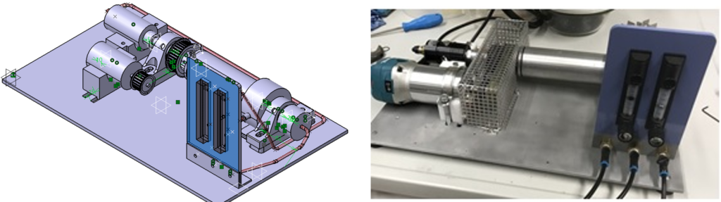
Within HYDROPTICS project, the use of liquid-liquid extraction techniques is of big importance. For such a process the phase separation of different liquids must be investigated. In order to separate the phases of one system, the application of centrifugal force appeared to have a significant impact. Such an application has a big advantage in variation of the centrifugal force strength that can be achieved through the change of rotational speed or dimensions of the equipment. The research in this direction shows that devices for performing such operation do exist in a big scale. However, the goal of this study is to develop a system for separation of two liquid phases, one being water and the other being cyclohexane, in lab scale device. Such a device is not known, so new concepts had to be developed. Preliminary design was done based on known big scale centrifuge device without any calculation to show the working principle. Few modifications as well as calculation were included before the first prototype was designed (see Fig. 1).
Simulation:
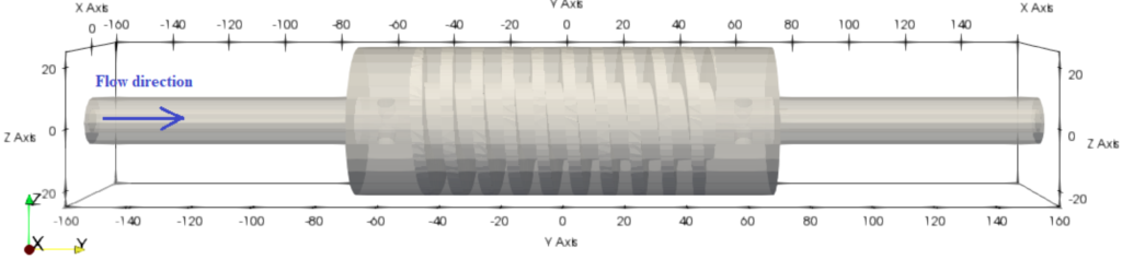
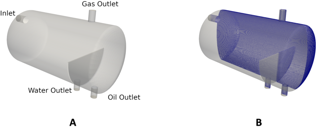
Multiphase flow presence is very wide in industry. Therefore, its investigation is important in order to predict such a behavior and additionally to optimize them for the best performance. Computational Fluid Dynamics (CFD) is a good way to achieve a good representation of such systems. Using CFD a different phenomenon consisting multiphase flows can be investigated. For the purpose of this study the twoPhaseEulerFoam solver of the open-source CFD toolbox OpenFOAM® was used. The twoPhaseEulerFoam is a multiphase solver employing the two-fluid concept for a continuous and dispersed phase. This investigation is dedicated to separation of a mixture water and cyclohexane in a lab-scale centrifugal separator. The separation zone is 50 mm diameter cylinder with 150 mm length. The mixture is introduced to the system via the feeding pipe of 8 mm diameter and is located in the shaft of the separation zone. The process is operated at ambient pressure (1 atm) and temperature of 20°C with Reynolds number of approximately 120. The geometry to be simulated is given in Fig. 2. Due to high requirement of such a simulations, detailed results will be presented in future.
Experiments:
The separation of water and cyclohexane was tested in experiment with designed first prototype. The procedure was as follows:
-
Mixture was prepared by taking approx. 10:1 volume ratio of water to cyclohexane, after it was mixed with hand-mixer for 1,5 min (2 x 45s);
-
The process was pumping the mixture to the system with a pump connected to power supply. Control of mixture pumping was achieved by a by-pass system and valve adjustment. The system was run by drilling machine.
-
After the steady state of the system was reached, the flow was adjusted to have about 50% to each outlet. The system was running with the drilling machine that could achieve approx. 1500 rpm max;
-
Sampling was made from 5 tests. The data is given in Table 1.
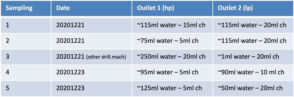
The conclusion was that at one outlet it was possible to reach almost clear phase while the other outlet was still containing the mixture. As outlets were designed in the manner to consist only one phase each (outlet 1 – heavy phase and outlet 2 – light phase), it would be the most desirable to achieve this behaviour in future design.
Digital Twin of an exemplary water treatment plant
An important area for monitoring and optimizing water treatment plants is represented by the simulation of such plants, which has recently become more and more detailed. The goal is to create a digital twin that represents the most important plant components and parameters in the overall simulation. Together with the sensors developed in the HYDROPTICS project, the combination of simulation techniques and sensing methods should provide the most accurate overview of the plant. This digital twin can subsequently be used for optimization in the area of monitoring and design of such plants. Furthermore, with the help of this simulations, conclusions can be drawn about possible alternative optimization methods.
Within the scope of the project, two aspects are addressed for the simulation of the test plants:
-
Process Simulation Model of the Overall Plant
-
CFD Simulations for a more detailed view on certain parts of interest
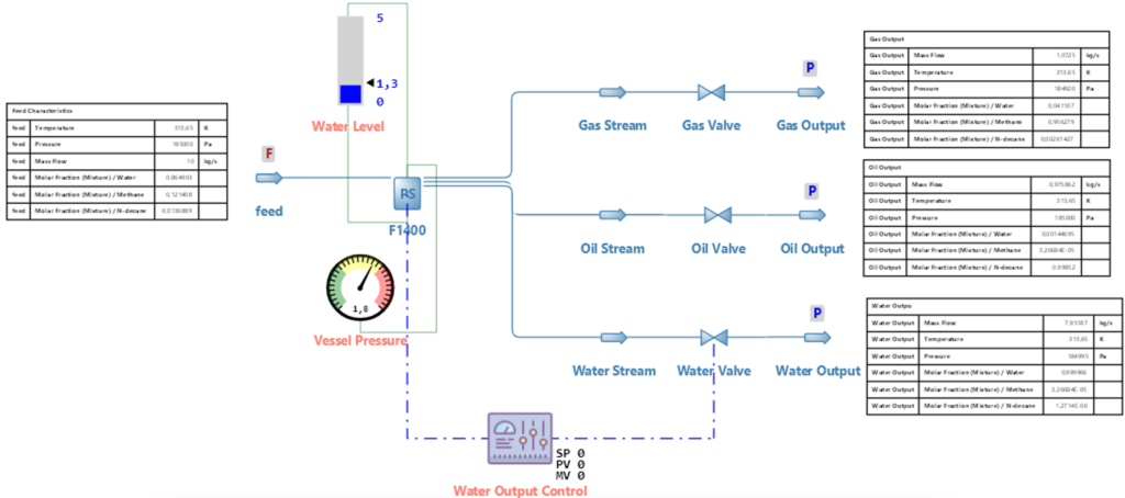
In the first step, the open-source process simulation software DWSIM is used to lay the foundation for the overall plant simulation. In close cooperation with the project partners in HYDROPTICS, user-defined models are created that represent the plant components in the test facilities and their dynamic behavior. The focus here is primarily on modeling the aqueous phase and the hydrocarbon compounds dissolved in it.
Subsequently, CFD simulations can provide a more detailed insight into different sub-processes within the plants. These simulations are performed with the OPENFOAM software package and certain models, which represent the characteristics of the corresponding components.
The combination of process simulation and CFD is used to provide an accurate overview of the entire plant and its characteristics. This combined simulation approach should provide new insights in the field of optimization and monitoring of such plants in the oil and gas industry.

Link: https://hydroptics.eu/wp-content/uploads/2021/06/Press_release_Process_simulation_16062021.pdf